Why Solar Charge Controller play a vital role in power storage systems
This article mainly introduces the types and uses of solar charge controllers. Solar charge controllers are an important component of outdoor RV systems and home solar energy storage systems. In this article, we will analyze the benefits of each controller, as well as their advantages and disadvantages. In fact, the solar charge controller is more important than you might think, because without it, we wouldn’t recommend any off-grid system, and for many good reasons. Common charge controllers on the market are PWM and MPPT.
Charge Controller Function
The main purpose of the controller is to prevent overcharging of the battery. The controller controls the battery charge level not to be higher than 100% by reading the battery level. This is an important function of the controller, because overcharging may damage the battery.
Another purpose of the controller is to charge the battery at the correct voltage level. This helps preserve battery life and health.
PWM Charge Controller
PWM (Pulse-width modulation) – Pulse-width modulation, is a method of reducing the average power delivered by an electrical signal, and represents the method they use to modulate electrical charge. PWM controllers have a more rudimentary charging function, as they mostly just drop the voltage from the panel to charge the battery, but the voltage drop causes power loss.
PWM Charge Controller Parameter
The PWM controller will have an amp reading, for example a 30A PWM controller. This represents how many amps the controller can handle, which in the above case is 30A. Typically, with a PWM controller, the two things you want to look at are amperage and voltage rating.
Please review the following controller electrical specifications
Model 1

First, we’re going to look at the Nominal voltage. This will tell us what battery pack voltage the controller is compatible with. In this case, you can use a 12V or 24V battery pack. Any higher voltage, like a 48V battery pack, the controller won’t work because the PWM controller can only lower the voltage, not raise it.
Second, we look at the rated charge current. We will use the above model in the chart as an example, in this case it is rated for 30 A. We recommend a safety factor of at least 1.25, which means you can multiply the panel’s current by 1.25 and compare it to 30 A.
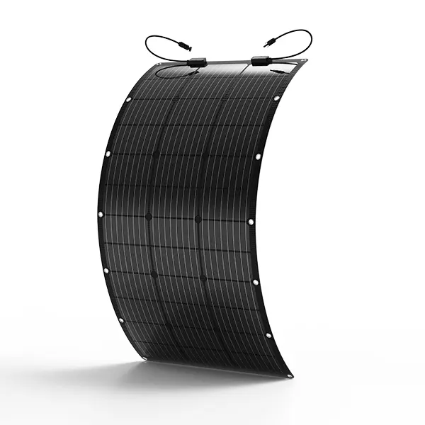
For example, 5*100 watt panels in parallel would be 5.56A x 5 = 27.8A. 27.8A x 1.25 = 34.75A, then 34.75>30,which is too much for the controller. The reason for this is that when the sunlight exceeds 1000W/m^2 or when it is tilted, the panel may be exposed to more current than the rated current.
Tips:5.56A-The data is derived from the operating current (IMP) in the parameters of the 100w solar panel.
Let’s see the calculation flow below.

Third, we’ll look at Max. Solar input. This tells you how many volts can go into the controller. The controller cannot accept more than 50 V. Let’s look at 2 x 100 watt panels in series with a total voltage of 22.5V (open circuit voltage) x 2 = 45 volts. 45<50.In this case, the two panels can be connected in series.
Fourth, we can look at the terminal. We can see that it can handle up to #8 AWG. This is important when purchasing wiring for your system.
Fifth, we can look at the battery type. These tell us which batteries are compatible with the charge controller. It’s important to check this as you don’t want the battery not being able to be charged by the controller unit.
MPPT charge controller

MPPT (Maximum power point tracking), is a technique used with variable power sources to maximize energy extraction as conditions vary. Represents maximum power point tracking, by controlling the voltage and current charging the battery, it is possible to find out the battery under any given conditions Maximum efficiency point for board charging. Using this method, the efficiency of the MPPT controller is actually 94-99%.
MPPT controllers have two important functions, one is that they can reduce the high voltage to match the voltage of your battery pack for proper charging. Second, while reducing the voltage, they increase the current strength to make up for the lost power, which is the biggest advantage of MPPT compared to PWM.
MPPT charge controller selection
The MPPT controller will have an amp reading, for example a 40 amp MPPT controller. Unlike PWM, the input voltage rating can be higher than the battery pack it will charge. This is due to the special properties of the MPPT controller, which is able to reduce the voltage to the battery pack voltage and then increase the current to make up for the lost power.
Please review the following controller electrical specifications
Model 2

First, we can see that this controller can handle 12V or 24V battery packs, as we did before.
Second, the current rating is 40 amps.
Third, we can look at the Max. solar input voltage, which in this case is 100 volts. This particular MPPT controller can accept 100 volt input. It will then drop this (up to) 100 volts to your 12V or 24V battery.
Let’s take a 400W(4*100W) system in series as an example. You have 4 panels of 100 watts each with an open circuit voltage of 21.6V. The 4 in series will be 4 x 21.6 V = 86.4 volts, which the controller can accept. Now if we ignore the boost current, we see that each circuit is only 5.56 amps, so if the controller is 40 amps, we divide the total current by the current in each parallel line (40/5.56 = 7.19) 7 strings, giving Do we bring 7*400=2800 watts? But why does the parameter sheet say that the maximum input power is 520 W? To answer this question, we need to understand the boost current.

At 2800 watts, 2800 watts / 12 V = 233 amps, 233 is greater than 40, which will definitely damage the controller. In fact, we use the maximum input power of 520 watts / 12V = 43 amps in the parameter table. This seems to be more than 40 amps, but we can ignore this result since 12V is a voltage you may never see. More precisely, you’d divide by the more common boost voltage (which you’ll learn about in the next section), so 520 watts / 14.4V = 36 amps. At this point 36 is less than 40. We can now see why the boost current is an important part of sizing the controller.

Boost current = solar array power/battery voltage, rather than simply comparing the sum of the parallel currents to the parameter table.
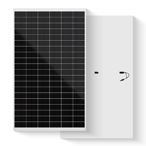
From the picture above, we can see that the solar panels that the controller can link to are determined according to the Max solar input power of the controller. The power limit of 520W can link 5 *100W solar panels, but for safety, it is best to link 4* 100W solar panels.
Charge Controller Mode
When your panel charges the battery pack, your controller will adjust their charging voltage levels based on the voltage levels of the batteries. These different voltage levels represent different charging phases.
Model 3

Equalization Charge Voltage: Equalization voltage is a voltage that you will most likely never see. It happens about every 20 days and it temporarily overcharges the battery to desulfurize the cells. This helps the health of the batteries and allows them to last longer. In this case of the controller in model 3, the equalizing voltage will vary depending on the type of battery you are using. In this case, you can also set the equalization voltage, which is beneficial for some batteries that require customer-set parameters.
Boost charging voltage: Boost charging is most of what you see when charging a battery. This is what most of the work is about. As you can see it varies for each battery type and in this particular controller the user can set its voltage level.
Float voltage: Use float when the battery is fully charged to prevent overcharging. Float charging will still charge the battery, but will reduce the voltage and current to equal the battery’s natural discharge rate, depending on the size of the battery pack.
Low Voltage Reconnect + Disconnect: This only applies to controllers with load terminals, Low Voltage Disconnect is the battery voltage level at which the load is cut off. Low voltage reconnect is the battery voltage level at which the load is turned back on.


